Part Geometry: The Limits of Thermal Spray Coatings
(Part 1 of 3)
Thermal spray coatings are not the end all be all. They aren’t the perfect, miraculous solution for all manufacturing wear and corrosion problems. This is probably not something you would expect a thermal spray company to say, let alone write an entire blog series about, but stick with me. In the late 1900’s thermal spray increased in popularity and people attempted to use it in scenarios without understanding the limitations. This scared some manufacturers away from thermal spray for good. It is in the best interest of everyone to learn, not only the benefits of thermal spray, but also, it’s limitations.
The first three we typically check when discussing thermal spray as a possible solution are the geometrical limitations, the coating thickness requirements, and the service environment of the part. To be as clear as possible we’ve split these topics into a series of blog posts on each of the three. The most inflexible limitation is usually part geometry. We’ll start there by exploring why the limitations exist, sharp edge and corner limitations, and inside diameter and line of sight limitations.
Why Does Thermal Spray Have Limitations?
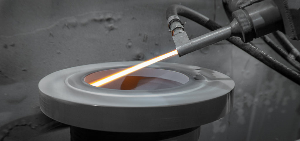
Before we get into the limitations of thermal spray, it is important to understand the mechanisms behind them. Most of the limitations, overall, are due to the nature of the bond that holds the coating material to the substrate. Thermal spray coatings are applied using heat and carrier gases to propel coating particles at high velocities onto the substrate. These splats form together to make the coating. This results in a mechanical bond. This type of bond makes certain loading scenarios off limits for thermal spray coatings. In addition, since the coating splats are propelled in this manner, there must be a clear line-of-sight for the coating to be applied properly. This method and the mechanical bond are behind most of the limitations of thermal spray but we’ll start with the ones concerning part geometry.
Sharp Edges and Corners

Since the coating bond is mechanical, if the coating is hit on an edge or a corner that has been coated, it will very likely crack or pop off. Gear teeth, for example, are not good candidates for a thermal spray coating since they, not only experience point loading, but also usually involve coating around a corner.
Corners become an issue due to the exposed edges of the coating. Even for cylindrical rolls it is generally preferred to have machining shoulders on either side of the coating to help protect the edge of the coating from chipping. Another common term for the shoulder that protects the coating is called a dam. If you can design the coating length and location this way, it can be blended into the shoulders during final grinding eliminating any contact with the edge of the coating in the operating environment.
The exception to this would be spray and fuse coatings. Although applied in a similar way to thermal spray coatings, they are fused afterwards by heating up the coating. This creates a metallurgical bond. These coatings often do better if they can go around an edge and often adhere better this way. Sharp edge and corner limitations can make thermal spray difficult on irregularly shaped parts. While not limited to, it works best for round, cylindrical parts and flat areas with no corner or edge loading. Another difficult geometry is inside diameter locations.
Inside Diameter and Line-of-Sight
Thermal spray is a line-of-sight process. Line-of-sight describes the direction the coating particles will flow from the spray gun. There must be a line-of-sight from the end of the gun to the coating location. Different thermal spray providers will have different limitations depending upon their thermal spray equipment. This affects many types of part geometry but is most prevalent for inside diameter, or I.D., coating locations.
In contrast, chrome plating is applied via a dip process. This type of coating can flow into small diameters and onto irregularly shaped areas. For a thermal spray coating to be applied to an inside diameter, with a traditional gun set up, the diameter of the bore must be greater than the desired depth of the coating.
There are inside diameter guns, or I.D. spray guns, that can go down into bores, etc. but they are only available for certain thermal spray processes and are different depending upon the thermal spray provider. The smallest feasible diameter is typically around 4” to 5” in diameter with the ability to go as deep as 24 to 48”. This mostly concerns inside diameter and bore coatings, but also apply to a part that requires coating on multiple faces. Since it is line-of-sight, the part must be positioned differently for very faces you coat. This can increase the price of thermal spray coating beyond feasibility.
Geometrical Limitations of Thermal Spray
These geometrical limitations are just the first checks when evaluating the feasibility of thermal spray as a coating solution. There are other exclusions that involve coating thickness capabilities and loading and operating environment tolerance. There are also exceptions to these geometrical limitations that specialized tooling can be used to overcome. The best way to determine feasibility is to work with a trusted thermal spray provider to evaluate specific parts and use cases.

- Choosing a selection results in a full page refresh.
- Press the space key then arrow keys to make a selection.
